CADworks3D, a Canadian 3D printer manufacturer and 3D materials developer, has introduced a state-of-the-art DLP 3D printer specifically designed for microfluidic applications: the ProFluidics 285D. This revolutionary machine is changing the way researchers think about fabricating microfluidic devices, offering an alternative to traditional fabrication techniques that are notoriously expensive, time-consuming, and labor-intensive.
Instead, the ProFluidics 285D enables workflows that are streamlined and easy to implement. It is a multi-purpose machine where this 3D printer can produce a variety of microfluidic devices, such as: B. transparent devices with encapsulated features, prototypes for PDMS devices and biocompatible devices or structures. Together with CADworks3D’s 3D materials line, researchers can reliably produce 100 µm channels and, depending on device design, smaller channels.
“The ultimate goal of CADworks3D is to support microfluidics researchers by providing them with an accessible 3D printing system that is affordable, easy to use and versatile – all without sacrificing high-resolution print quality.”
Figure A. ProFluidics 285D technical specifications. Image via CADworks3D.
How does standard DLP 3D printing work?
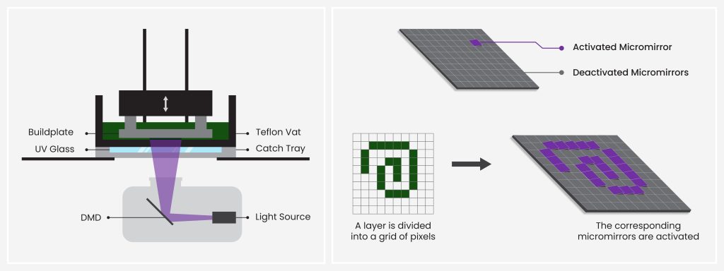
Digital Light Processing (DLP) is one of the most commonly used technologies in vat polymerization 3D printing or resin 3D printing, which translates digital computer-aided design (CAD) into usable 3D objects. The backbone of this technology is a digital projector that shines UV light onto a series of microscopic mirrors called a Digital Micromirror Device (DMD). These mirrors reflect UV light onto a layer of photosensitive resin, causing it to harden into the shape of the object being printed. This is repeated layer by layer until a complete object is created. (See Figure B, left side).
A CAD file is broken down into layers, similar to the section of a CT scan. Each layer is further divided into a grid of pixels, where each pixel corresponds to a single mirror in the DMD. When printing a layer, the projector activates the mirrors according to the pixels needed to create the CAD file. When the mirrors are activated, they reflect UV light onto the liquid resin, curing it with pixel precision. When mirrors are disabled, they do not light up and the resin areas remain uncured. (See Figure B, right side) Projected pixel size is expressed in micrometers (µm) and corresponds to the XY resolution listed in a printer’s technical specifications.
How the ProFluidics 285D outperforms standard DLP 3D printing:
Print exceptionally smooth curves and shapes
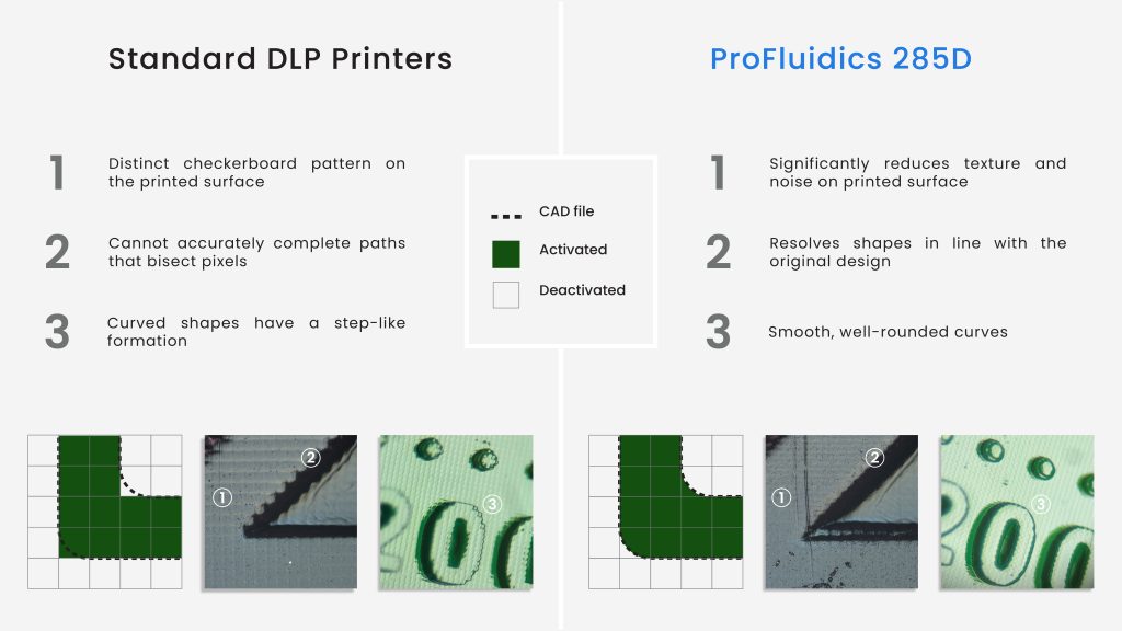
What happens if parts of the CAD file cut pixels in half? Standard DLP printers evaluate how much of the design a given pixel covers and use a binary rounding function to either enable or disable the entire pixel during printing. The result is a device with a noticeable checkerboard pattern on the surface and a step-like curve (see Figure C, left side). The device often differs from the original CAD file.
The ProFluidics 285D addresses this problem with its dynamic pixel advantage. With a dynamic XY resolution of 28.5 µm, the ProFluidics 285D offers significant improvements in the precise resolution of design features – even those that cut pixels in half. Printed devices closely resemble the intended design and the appearance of cube patterns and noise are minimized compared to existing available platforms (see Figure C, right side). With this technology, the ProFluidics 285D can successfully print features with 180-degree curves, complex serpentine channels, and other complicated geometries.
Application 1: Clear encapsulated devices
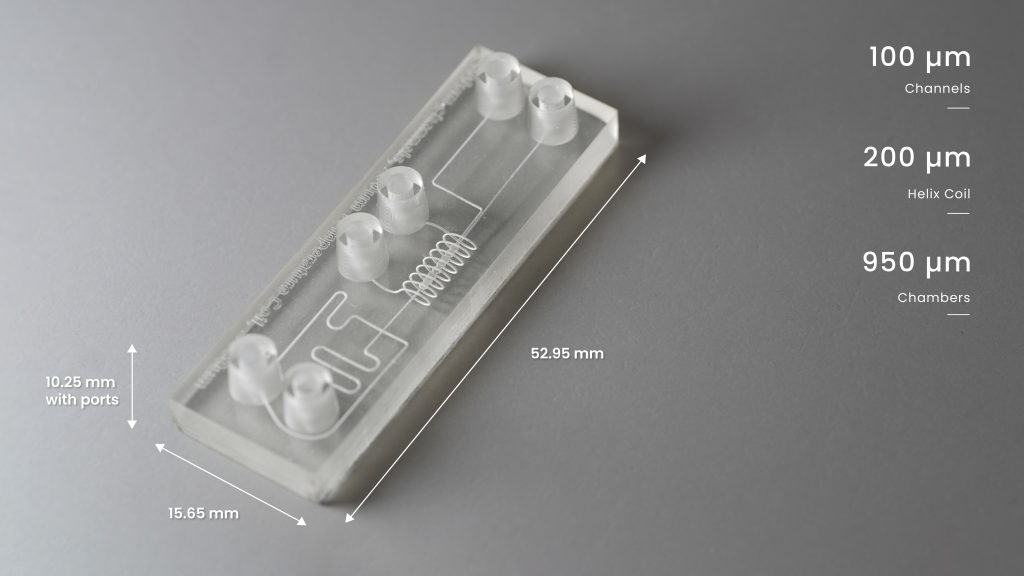
The ProFluidics 285D can produce several categories of microfluidic devices, the first being transparent devices with encapsulated channels and functions.
The viability and size of these encapsulated channels are critical aspects of these devices, and CADworks3D’s Clear Microfluidics Resin makes the ProFluidics 285D stand out. Devices can be manufactured in just one print job without the need to assemble multiple parts, and encapsulated channels printed using the XY process can be up to 80 μm in size. Researchers can also create more novel designs that incorporate variations in Z heights, such as helical coils (see Figure D).
Post-processing is a quick and easy process. Depending on the height of the device, the entire process of printing a ready-to-use device can be completed in just over an hour. No surface coating or polishing is required to achieve optical transparency, eliminating multiple, often lengthy post-processing steps required with other methods and materials. The Clear Microfluidics Resin is inert under fluorescent light and is therefore suitable for microscopy and imaging.
Application 2: Prototype for PDMS devices
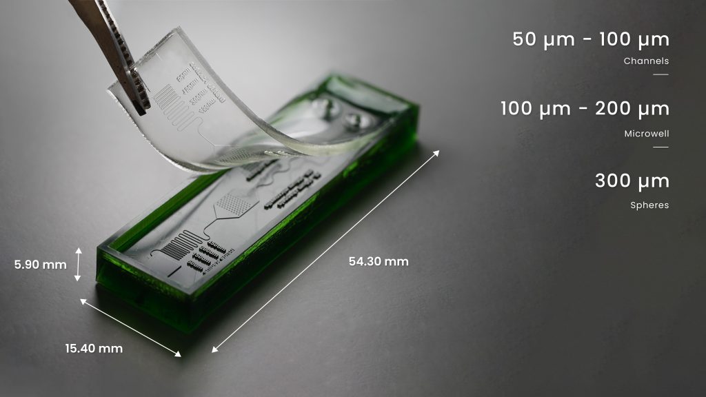
When using traditional techniques such as photolithography, producing master molds is expensive, time-consuming and laborious. The ProFluidics 285D moves the production of the master molds from the clean room to the workbench, thereby speeding up the process significantly. Researchers gain the ability to 3D print, clean, and cure a master mold in just a few hours, and within one business day, a PDMS device can be cast and ready for bonding to a substrate.
CADworks3D’s Master Mold for PDMS Device Resin allows you to print molds with channel widths as small as 50 µm. The printed shapes exhibit exceptional detail and smoothness with an average measured Ra value of 0.18 µm. These printed master molds are very durable, can withstand the temperatures required to cast and cure PDMS in an oven, and can be used repeatedly to cast hundreds of PDMS devices from one master.
The photopolymer resin is formulated to eliminate the need for release agents, coatings, and other pretreatment processes for successful, clean PDMS casting. Additionally, the printed master does not release chemicals into the cast PDMS, so the resulting PDMS devices retain their biocompatible properties.
Application 3: Biocompatible devices and structures
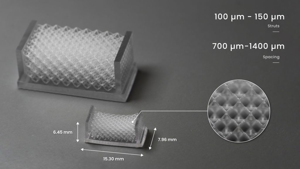
Expanding on the theme of biocompatible devices, the ProFluidics 285D works with an open materials system, giving users the ability to print with third-party materials. It houses a projector equipped with a 385nm LED light source and therefore the ProFluidics 285D can print with several biocompatible 3D resins available on the market for applications such as bioscaffolds (see Figure F).
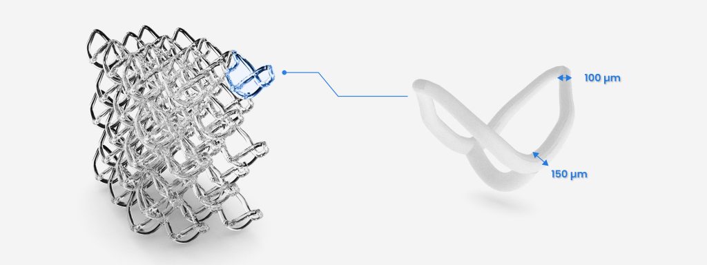
A unique feature of 3D printing bioscaffolds is the ability to print an offset lattice (see Figure G). This creates a more random structure, allowing cells to grow along the bias and allowing for a more even distribution of growth. Using the Detax Freeprint Ortho Resin as an example, the ProFluidics 285D is capable of printing bioscaffolds in just over an hour with struts of up to 100 µm and spacings between 700 µm and 1400 µm.
Designed to strengthen microfluidics research
The existing 3D marketplace typically offers microfluidics solutions adopted from other industries. Therefore, there is often a gap or complete mismatch between the needs of a researcher and the capabilities of a printer. Microfluidic devices require printed features smaller than 100 micrometers, and many common platforms do not offer the required size or quality.
ProFluidics 285D and CADworks3D materials are designed exclusively for microfluidic applications. Together, they offer researchers a complete package that meets the demand for finer printed features with minimum channel sizes of 80 µm and 50 µm for encapsulated and open channels, respectively. It enables new, innovative workflows that save researchers time, effort and money. It becomes possible to make three to five devices in just a few hours, with a cost of about $2.05 to $2.55 at 5g per device. When compared to traditional manufacturing methods or the cost of outsourcing manufacturing to third-party 3D printing services, the benefits of working with a complete in-house 3D printing platform become clear.
The picture shown shows the ProFluidics 285D. Photo via CADworks3D.

